
jl audio wiring guide
JL Audio Wiring Guide: A Comprehensive Overview (01/26/2026)
This comprehensive guide details JL Audio system installation, troubleshooting, and optimal performance through correct wiring practices. Diagrams and configurations are essential for success.
JL Audio systems are renowned for their superior sound quality and robust performance, but achieving this potential hinges on meticulous wiring. Proper installation isn’t merely about connecting wires; it’s about ensuring a clean, efficient, and safe power delivery and signal path. A well-executed wiring scheme minimizes interference, maximizes amplifier efficiency, and safeguards your investment from potential damage.
Understanding the fundamentals of car audio wiring, specifically as it relates to JL Audio components, is crucial. This involves recognizing different wire gauges, connection types, and the importance of grounding. Incorrect wiring can lead to a host of issues, from poor sound quality and system instability to blown fuses and even amplifier failure. This guide will provide a foundational understanding, empowering you to tackle JL Audio wiring projects with confidence and precision.
Why Use a Wiring Diagram?
Navigating a JL Audio system installation without a wiring diagram is akin to assembling a complex puzzle without the picture on the box. The sheer number of wires, connections, and components can quickly become overwhelming, increasing the risk of errors. A diagram serves as a visual roadmap, clearly illustrating how each element connects and interacts with the others.
Wiring diagrams minimize guesswork, preventing incorrect connections that could damage your equipment. They ensure proper polarity, correct gauge wire usage, and appropriate fuse placement. Furthermore, diagrams are invaluable for troubleshooting. When issues arise, a diagram allows you to systematically trace the wiring, identify potential faults, and resolve problems efficiently. Utilizing a diagram saves time, reduces frustration, and ultimately guarantees a high-performing, reliable audio system.
Understanding JL Audio Amplifier Wiring Basics
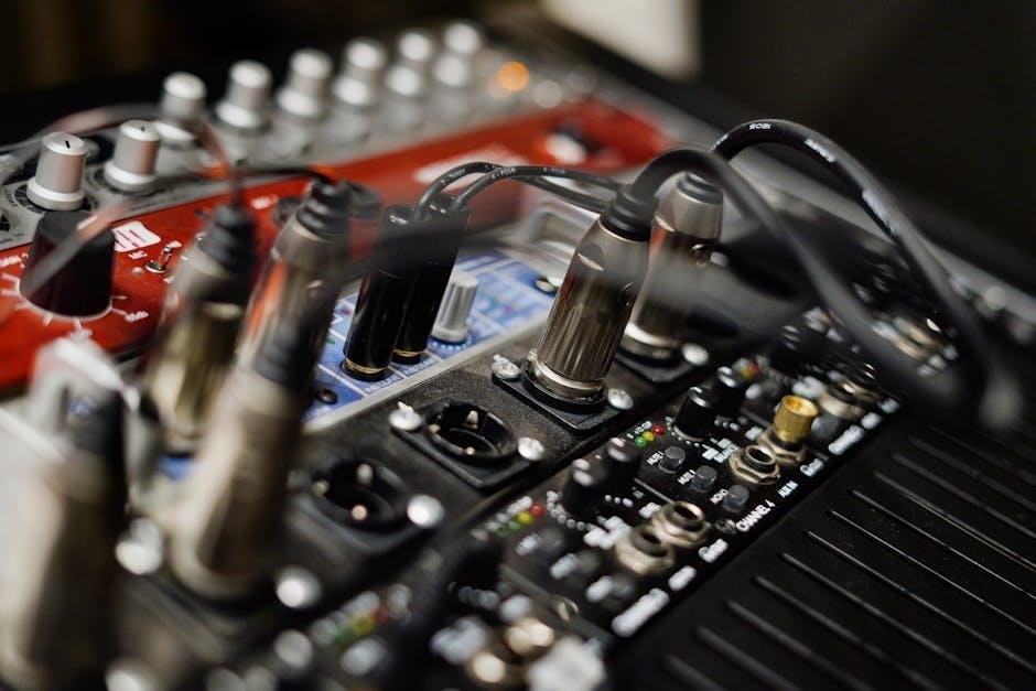
JL Audio amplifier wiring centers around four core connections: Power, Ground, Remote Turn-On, and Signal (RCA). The Power wire, typically red, delivers 12V+ from the vehicle’s battery, requiring a fuse near the battery for safety. The Ground wire, usually black, provides a return path for the current, needing a solid chassis connection.

The Remote Turn-On wire, often blue, signals the amplifier to power on/off with the head unit. Finally, RCA cables carry the audio signal. Understanding wire gauge is crucial; thicker wires handle more current. Proper connections are vital – secure, clean connections minimize resistance and ensure optimal performance. Always disconnect the negative battery terminal before beginning any wiring work to prevent shorts.

Wiring Components & Tools
Essential components include wires, connectors, fuses, and a distribution block. Necessary tools are wire strippers, crimpers, a multimeter, and a screwdriver for a successful installation.
Essential Wiring Tools
For a professional JL Audio wiring installation, having the right tools is paramount. Wire strippers are crucial for cleanly removing insulation without damaging the conductor. A high-quality crimping tool ensures secure connections, preventing signal loss and potential shorts. Don’t underestimate the value of a reliable multimeter; it’s essential for verifying voltage, continuity, and resistance, aiding in troubleshooting.
Screwdrivers (various sizes) are needed for mounting amplifiers and connecting to vehicle wiring. Pliers assist with manipulating wires and connectors. A wire tracer can be invaluable for identifying wires within a vehicle’s harness. Consider a digital signal processor (DSP) tuning tool for advanced system optimization. Finally, heat shrink tubing and a heat gun provide excellent insulation and protection for connections, enhancing durability and safety.
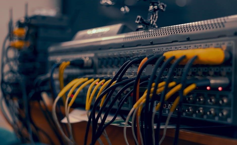
Types of Wiring Used in JL Audio Systems
JL Audio systems utilize several wiring types, each serving a specific purpose. Power wire, typically thicker gauge, delivers current from the battery to the amplifier. Ground wire provides the return path for the current, crucial for system stability. Speaker wire connects the amplifier to the speakers, transmitting the audio signal; oxygen-free copper (OFC) is preferred for clarity.
RCA cables carry the audio signal from the head unit to the amplifier, shielded to minimize interference. Remote turn-on wire signals the amplifier to power on/off with the head unit. High-quality interconnects are vital for a clean signal. Finally, consider using shielded twisted pair (STP) wiring for sensitive connections, further reducing noise and ensuring optimal audio performance within your JL Audio setup.
Understanding Gauge and Wire Size
Wire gauge is inversely proportional to wire thickness; a lower gauge number indicates a thicker wire. JL Audio systems demand appropriate wire sizing to handle current flow efficiently and prevent voltage drop. For power and ground wires, 4-gauge or 0-gauge are common for high-power amplifiers, while 12-gauge or 14-gauge suffices for smaller setups.
Speaker wire gauge depends on distance and power; 16-gauge is suitable for shorter runs, while 14-gauge or 12-gauge is better for longer distances. Always consult JL Audio’s documentation for specific recommendations. Using undersized wire can lead to overheating, reduced performance, and potential damage. Proper wire size ensures optimal power delivery and a clean, powerful audio signal.

JL Audio Amplifier Wiring Configurations
Various JL Audio amplifier setups exist, including 4-channel, mono (subwoofer), and multi-amplifier configurations, each requiring specific wiring schemes for optimal performance.
4-Channel Amplifier Wiring
Wiring a 4-channel JL Audio amplifier involves connecting it to four speakers – typically front left, front right, rear left, and rear right. Begin with the power and ground connections, ensuring a secure and clean connection to the vehicle’s electrical system. Next, run the speaker wires from the amplifier to each respective speaker, paying close attention to polarity (positive and negative). Incorrect polarity can result in phase cancellation and poor sound quality.
Utilize a wiring diagram specific to your amplifier model to identify the correct input and output connections. For bridged configurations, where two channels are combined to power a single speaker, consult the amplifier’s manual for detailed instructions. Proper gauge wire is crucial; thicker wire is needed for longer runs and higher power outputs. Always use high-quality connectors and ensure all connections are insulated to prevent shorts and interference. Finally, double-check all wiring before powering on the system.
Mono Amplifier Wiring (Subwoofer)
Wiring a mono JL Audio amplifier, designed for subwoofers, requires careful attention to impedance matching and power delivery. Start by connecting the amplifier’s power and ground wires, utilizing appropriately sized gauge wire based on the amplifier’s power output and wire length. Connect the remote turn-on wire to activate the amplifier when the head unit is powered on.
Next, wire the subwoofer to the amplifier, ensuring the correct impedance load is presented. Mono amplifiers are typically wired in parallel or series to achieve the desired impedance. Consult your amplifier’s manual for specific wiring configurations. Pay close attention to polarity; incorrect wiring can cause the subwoofer to perform poorly. Secure all connections and insulate them properly to prevent shorts. Verify all wiring before powering up the system to avoid damage;
Wiring Multiple Amplifiers
When installing multiple JL Audio amplifiers, proper power distribution is crucial. A distribution block should be used to split the power wire from the battery, ensuring each amplifier receives adequate voltage. Utilize separate ground wires for each amplifier, connecting them to solid chassis points as close to the amplifiers as possible.
The remote turn-on wire can be daisy-chained, but a dedicated wire for each amplifier is recommended for reliability. Consider using a signal processor (DSP) to manage signal distribution to each amplifier, allowing for independent control and equalization. Always fuse each amplifier individually, close to the power source, for safety. Double-check all connections before powering on the system to prevent damage and ensure optimal performance.

Specific JL Audio Amplifier Series Wiring
JL Audio offers diverse amplifier series—HD, XD, and JX—each with unique wiring requirements. Consult specific manuals for optimal installation and performance.
HD Series Amplifier Wiring
The JL Audio HD Series amplifiers are renowned for their high power and robust build quality, demanding meticulous wiring for optimal performance. These amplifiers typically require substantial power and ground connections, utilizing heavy-gauge wiring to handle the current draw. Proper grounding is crucial; connect the ground wire directly to the vehicle’s chassis, ensuring a clean and solid connection free from paint or corrosion.
When wiring HD Series amplifiers, pay close attention to the remote turn-on wire, ensuring it’s securely connected to the head unit’s remote output. Input connections should be made with high-quality RCA cables, shielded to minimize interference. Speaker wiring requires appropriate gauge wire based on impedance and distance, following JL Audio’s recommendations. Always utilize a properly sized fuse near the battery to protect the system. Refer to the specific HD Series amplifier manual for detailed wiring diagrams and specifications, as configurations vary between models.
XD Series Amplifier Wiring
JL Audio’s XD Series amplifiers offer a balance of power and efficiency, making them popular for various car audio setups. Wiring these amplifiers requires careful attention to detail to ensure optimal performance and reliability. Like the HD series, a robust power and ground connection are essential, utilizing appropriately sized gauge wiring based on the amplifier’s power output.
Grounding should be directly to the vehicle chassis, cleaned of any paint for a solid connection. The XD series often incorporates advanced features like automatic turn-on, but a dedicated remote wire is still recommended for consistent operation. High-quality RCA cables are vital for clean signal transfer, minimizing noise. Speaker wiring should match impedance and distance guidelines. Always install a fuse near the battery, sized correctly for the amplifier’s current draw. Consult the specific XD Series amplifier manual for detailed wiring schematics.
JX Series Amplifier Wiring
The JL Audio JX Series amplifiers represent an excellent entry point into high-performance car audio, offering a compelling blend of features and affordability. Wiring a JX amplifier demands adherence to best practices for optimal sound quality and system longevity. Prioritize a clean, direct power connection from the vehicle’s battery, utilizing appropriately gauged wiring determined by the amplifier’s power rating.
A solid ground connection to the chassis is crucial, ensuring minimal resistance and noise. While the JX series often features high-level inputs, utilizing RCA interconnects delivers superior signal clarity. Speaker wiring should be selected based on impedance and run length. Don’t forget a properly sized fuse near the battery for safety. Always refer to the specific JX amplifier’s manual for detailed wiring diagrams and specifications.

Vehicle-Specific Wiring Guides
Detailed wiring schematics for specific vehicles, like the Jeep JL Wrangler, simplify installation and ensure compatibility with factory systems and components.
Jeep JL Wrangler Audio System Wiring Diagrams
Accessing accurate wiring diagrams is crucial for a seamless JL Wrangler audio upgrade. Several diagrams cater to different Wrangler configurations, including base and premium audio systems. These PDFs detail the connections for various components like the radio, speakers, amplifiers, and auxiliary systems.
Available diagrams also cover the automatic sway bar, axle locker system, backup camera, backup lamps, and even the blind spot monitoring system. Understanding the CAN C bus layout and system wiring is vital for integrating aftermarket JL Audio equipment without causing electrical conflicts. Downloadable resources include individual files for each system, or a comprehensive ZIP file containing all diagrams for convenient access during installation. Proper integration requires careful attention to these vehicle-specific schematics.
General Car Audio Wiring Considerations
Beyond vehicle-specific diagrams, several universal principles apply to all car audio installations, especially with JL Audio components. Maintaining a clean and organized wiring layout is paramount, preventing shorts and signal interference. Always prioritize proper grounding techniques, ensuring a solid connection to the vehicle’s chassis for optimal performance and noise reduction.
Careful attention to wire gauge is essential; insufficient gauge can limit power delivery and compromise sound quality. Utilize high-quality connectors and shielding to minimize signal loss and external noise. Remember to fuse all power wires close to the battery for safety, protecting both the equipment and the vehicle. Thoroughly insulate all connections to prevent shorts and ensure a reliable, long-lasting installation.
Factory Radio Integration Wiring
Integrating JL Audio amplifiers with a factory radio often requires specific interfaces to maintain features like steering wheel controls and factory display functionality. Line Output Converters (LOCs) are frequently used to tap into the factory radio’s speaker wires, converting the high-level signal to a low-level RCA output suitable for amplifiers.
However, higher-quality integration solutions, such as those utilizing the vehicle’s CAN bus system, offer superior signal quality and feature retention. Ensure compatibility between the chosen interface and both the factory radio and the JL Audio amplifier; Proper wiring and configuration of these interfaces are crucial for avoiding noise and ensuring seamless operation. Consult vehicle-specific guides for detailed wiring instructions.
Troubleshooting Common Wiring Issues
Identifying shorts, grounding faults, and signal interference are key to resolving audio problems. Careful inspection and testing are vital for a functional system.
Identifying Short Circuits
Short circuits represent a significant threat to your JL Audio system, potentially causing damage to amplifiers, wiring, and even the vehicle’s electrical system. A short occurs when a live wire unintentionally connects with a ground or another live wire, creating a low-resistance path for current. This results in excessive current flow, often triggering fuses to blow, but repeated failures indicate a deeper issue.
Visually inspect all wiring for damaged insulation, pinched wires, or exposed conductors. Pay close attention to areas where wires pass through metal panels or near sharp edges. Use a multimeter in continuity mode to test for unintended connections between wires and ground. Disconnect power before testing! If a short is suspected but not immediately visible, disconnect components one by one – speakers, RCA cables, remote turn-on wire – until the short is isolated. Remember stray wires can also cause shorts.
Dealing with Grounding Problems
Grounding issues are a frequent source of noise and malfunction in JL Audio systems. A poor ground connection creates a high-resistance path for return current, leading to voltage drops and unwanted electrical interference. Symptoms include engine noise, whining sounds, or complete amplifier shutdown. Proper grounding is crucial for stable operation and optimal sound quality.
Ensure the amplifier’s ground wire is securely connected to a clean, unpainted metal surface on the vehicle’s chassis. Scrape away any paint or corrosion to establish a solid connection. Keep the ground wire as short as possible – ideally under 18 inches – and use a wire gauge equal to or larger than the amplifier’s power wire. Multiple ground points are sometimes necessary for high-power systems. Verify ground continuity with a multimeter; resistance should be near zero ohms.
Resolving Signal Interference
Signal interference manifests as unwanted noise – hissing, popping, or alternator whine – polluting the audio signal. Several factors contribute to this, including proximity of signal wires to power cables, inadequate shielding, and ground loops. Addressing these issues is vital for a clean, high-fidelity sound.
Run RCA cables on the opposite side of the vehicle from the power wire, maintaining maximum distance between them. Utilize high-quality, shielded RCA cables to minimize external noise pickup. Employ a ground loop isolator if a ground loop is suspected, particularly when integrating with a factory radio. Ensure all connections are secure and free from corrosion. Consider a digital signal processor (DSP) to further refine the signal and filter out unwanted frequencies. Proper wire routing and component selection are key.

Advanced Wiring Techniques
Mastering DSP integration, remote turn-on wire configurations, and precise fuse selection unlocks the full potential of your JL Audio system for optimal performance.
Using a Digital Signal Processor (DSP)
Integrating a Digital Signal Processor (DSP) with your JL Audio system elevates audio quality to a professional level. DSPs allow for precise control over various audio parameters, including equalization, time alignment, and crossover points. This fine-tuning capability compensates for vehicle acoustics and speaker placement limitations, resulting in a remarkably clear and balanced soundstage.
When wiring a DSP, ensure proper connections to the amplifier’s inputs and outputs. Utilize high-quality RCA cables to minimize signal loss and interference. Configure the DSP’s settings carefully, starting with basic equalization adjustments to address frequency response imbalances. Time alignment is crucial for synchronizing sound arrival from each speaker, creating a focused imaging experience. Experiment with crossover settings to optimize speaker performance within their designated frequency ranges. Remember to save your DSP profiles for future reference and adjustments.
Remote Turn-On Wire Configuration
The remote turn-on wire is crucial for activating your JL Audio amplifier when the vehicle’s head unit is powered on. Typically, this wire (often blue) receives a +12V signal from the head unit, signaling the amplifier to switch from standby to operational mode. Proper configuration ensures the amplifier powers up and down in sync with the vehicle’s ignition.
Connect the amplifier’s remote turn-on input to the head unit’s designated remote output. Avoid connecting it directly to a constant +12V source, as this will drain the battery. If your head unit lacks a remote output, a relay triggered by the accessory power can be used. Securely connect the wire and ensure a clean, solid connection to prevent intermittent operation. Verify functionality by testing the amplifier’s power-on behavior with the ignition.
Proper Fuse Selection and Placement
Fuses are vital safety components protecting your JL Audio system from overcurrent and potential damage. Selecting the correct fuse amperage is paramount; it should closely match the amplifier’s specified current draw, typically found in the amplifier’s manual. Always err on the side of slightly higher amperage than the calculated draw, but never exceed the amplifier’s maximum fuse rating.
Place fuses as close as possible to the power source (battery) and the amplifier. This minimizes the length of unprotected wiring. Use high-quality fuse holders designed for automotive applications. A fuse within 18 inches of the battery is critical for preventing damage to the entire power cable run. Regularly inspect fuses for signs of corrosion or damage, replacing them as needed to maintain system safety and reliability.
Safety Precautions
Prioritize safety by disconnecting the battery, insulating all connections thoroughly, and meticulously avoiding any stray wires during JL Audio system installation.
Disconnecting the Battery
Before commencing any JL Audio wiring work, completely disconnecting the vehicle’s battery is paramount for safety. This prevents accidental short circuits that could damage the amplifier, wiring, or even the vehicle’s electrical system. Locate the negative terminal of the battery – it’s typically black. Using a wrench, carefully loosen the nut securing the negative cable to the terminal.
Once loosened, gently remove the cable from the terminal, ensuring it doesn’t accidentally touch any metal parts of the vehicle. Secure the disconnected cable away from the battery terminal to prevent accidental reconnection. Always disconnect the negative terminal first. This minimizes the risk of sparking. Remember to have your radio security code available if required upon reconnection, as disconnecting the battery may reset some vehicle systems.
Insulating Connections
Properly insulating all electrical connections is crucial for a reliable and safe JL Audio system. Exposed wires can cause short circuits, leading to system malfunction or even fire hazards. Utilize high-quality heat shrink tubing over each connection after crimping or soldering. Ensure the tubing is sized appropriately for the wire gauge and fully covers the exposed metal.
Apply heat using a heat gun (preferred) or a lighter, carefully shrinking the tubing to create a tight, protective seal. Electrical tape can be used as a secondary layer of insulation, but it’s less durable than heat shrink. Pay close attention to grounding connections, ensuring they are securely fastened and well-insulated to prevent unwanted noise or interference. Avoid leaving any stray wires uninsulated.
Avoiding Stray Wires
Stray wires represent a significant risk within any car audio installation, particularly with powerful JL Audio systems. These loose ends can cause short circuits, ground loops, and signal interference, degrading audio quality and potentially damaging components. Securely route all wiring harnesses, utilizing zip ties or wire loom to bundle and organize them neatly.
Ensure no bare wire is exposed, and any unused wire lengths are trimmed and properly insulated; Keep power and signal wires separated to minimize noise. Avoid running wires near antennas or other sources of electromagnetic interference. Regularly inspect the wiring under seats and within panels to identify and address any potential stray wires before they become problematic. A clean, organized wiring layout is essential for a reliable system.